Joist Load Bearing Calculator — Uniform Loads, Point Loads & Bearing Stress
A joist fails three ways, not one: it bends, it shears, or its end crushes where it bears. Set the span, the loads and the bearing seat below — the calculator checks all three at once and tells you which one is closest to its limit.
Joist Load Bearing Calculator
Bending, shear and bearing checked together — the three ways a joist carries load.
✓ preview: 14' 0"
Load capacity verdict
HOLDS
SPF 2×10 at 16″ o.c. · 40/10 psf
Bending utilization
83%M = 19,600 in-lb vs 23,677 capacity
Shear utilization
37%max reaction 467 lb at the support
Bearing utilization
49%207 psi on the 1.5″ seat vs 425 psi allowed (Fc⊥ SPF)
Uniform live capacity
50 psf
on top of 10 psf dead, bending-governed
Point-load headroom at midspan
97 lb
with the 40/10 psf floor already on
Capacity = the smallest of bending, shear and bearing. Fc⊥ values: SYP 565, DF-L 625, SPF 425, Hem-Fir 405 psi (NDS No. 2). Uniform and point loads are superimposed conservatively — real interactions are slightly kinder.
What Each Load Parameter Actually Does
A joist load calculation is six inputs deep, and each one feeds a different failure mode. This is the table to read before trusting any number — including the calculator's.
| Input | What it sets | The mechanism | Risk if wrong |
|---|---|---|---|
| Tributary width (spacing)Core | Converts floor psf into the line load one joist actually feels | Each joist carries half the bay to its left and half to its right — 16″ o.c. means 16/12 ft of floor feeds every foot of joist | Reading a psf table without tributary width overstates capacity by up to 2× |
| Live load (psf) | The movable weight code assumes: people, furniture, snow | IRC default 40 psf for living areas, 30 for bedrooms; it drives bending and deflection | Swapping 40 → 100 psf quadruples the line load and breaks undersized bearing seats |
| Dead load (psf) | The permanent weight: subfloor, finishes, ceiling below | Standard 10 psf; tile or double floors push 15–20 psf into every bending and bearing number | Forgetting a heavy finish trims real margins by 10–30% |
| Point load (lb) & positionCore | Localized weights: RTUs, safes, tubs, bearing walls above | A midspan point load bends the joist 2× harder than the same load split to the ends (M = P·L/4 vs reactions only) | One 500 lb safe at midspan can consume the entire bending budget a 40 psf floor leaves |
| Bearing length (in)Core | The contact seat the reaction squeezes through | Bearing stress = reaction ÷ (bearing length × thickness); wood crushes perpendicular to grain at Fc⊥ (425–625 psi) | A 1.5″ seat on soft SPF at high load creeps and visibly squashes over months |
| Fc⊥ (psi) | The species' resistance to crushing across the grain | SYP 565, DF-L 625, SPF 425, Hem-Fir 405 psi — the failure is compression, not bending | Sizing for bending alone misses the slow crush that sags floors near supports |
Tributary-area shortcut
Point loads spread through the floor: a safe sitting on 4 sq ft of subfloor delivers its weight to roughly the two nearest joists. Multiply any concentrated weight by the fraction of floor it occupies, then verify those joists directly.
The 2× midspan trap
The same point load at midspan creates twice the bending moment of the load dropped near a support. Before adding weight to a floor, slide it toward a bearing line — position is worth more than joist size.
Don't trust the floor's feel
Stiff floors hide overloaded bearing: a joist can be crushing at its seat for years with no sag you can see. Bearing damage is found by probing the seat, not by walking the room.
Bearing Stress: The Check Everyone Skips
Bearing stress is the reaction force pressed through the contact patch where the joist meets its support:
bearing stress = reaction ÷ (bearing length × joist thickness)
Wood crushes across the grain at a known pressure — Fc⊥ — which ranges from 425 psi (SPF) to 625 psi (DF-L) for No. 2 framing. Stay under it and the seat lasts forever; exceed it and the joist slowly compresses, dropping the floor a fraction of an inch at a time right where nobody looks.
Code minimum bearing lengths
- 1½″ minimum on wood or metal (a sill plate or hanger seat)
- 3″ minimum on concrete or masonry (foundation walls, steel beams)
- 3″+ at interior beam bearings — several provincial codes call for a 3¼″ seat at interior supports
Where joists differ
- Floor joists — reactions from full live load; watch every seat at beams and rim connections
- Deck joists — hangers replace most seats; the ledger fasteners become the bearing
- Ceiling joists — light reactions, but attic storage converts them to floor-grade loads
What Higher Live Loads Do to a Bearing Seat
One 14 ft SPF 2×10 at 16″ o.c., reaction into a 1½-inch plate seat vs a 3-inch beam seat. At 100 psf the 1½-inch seat is over its 425 psi limit — the same reaction on the 3-inch seat idles at half of it.
| Live load | End reaction (14 ft span) | Stress on 1½″ seat | Stress on 3″ seat |
|---|---|---|---|
| 40 psf | 467 lb | 207 psi — ok | 104 psi — ok |
| 50 psf | 560 lb | 249 psi — ok | 124 psi — ok |
| 100 psf | 1027 lb | 456 psi — over | 228 psi — ok |
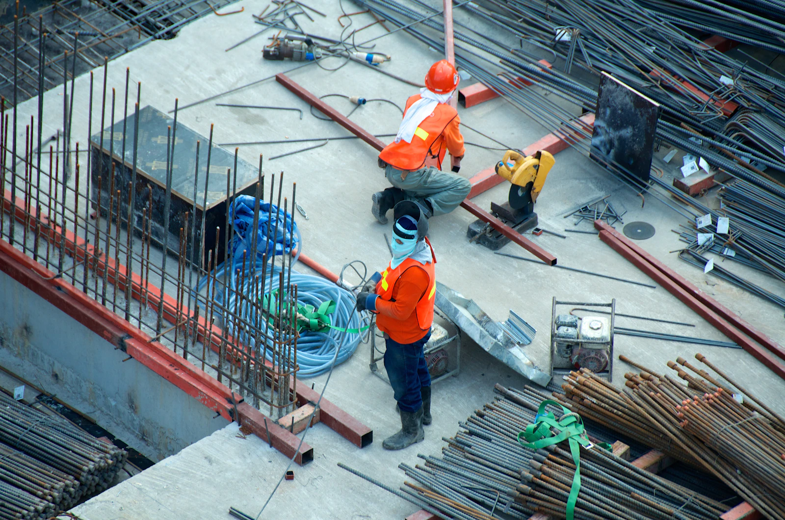 Every load a joist carries ends here: the bearing seatPhoto: Unsplash
Uniform, Point and Line Loads — and the RTU Test Case
Three load shapes reach a joist, and each stresses it differently. Knowing which one you have is half the calculation.
Uniform load
Spread evenly: people, furniture, flooring. Feeds every check: M = wL²/8, reaction = wL/2, deflection = 5wL⁴/384EI. The 40 psf code number is a uniform assumption — real rooms only approximate it.
Point load
One location: safes, tubs, RTUs, a bearing wall above. At midspan it bends twice as hard as the same weight at the ends (M = P·L/4). Reactions split by position — R₁ = P·b/L, R₂ = P·a/L — so one end's bearing takes more.
Line load
A wall or partition running perpendicular across several joists, or parallel directly over one. A parallel wall doubles one joist's line load; a perpendicular wall becomes a row of point loads that needs a header or doubled joists beneath.
800 lb RTU on an existing floor
A rooftop-style condenser unit lands on a curb over a 14 ft floor framed with 2×10 SPF at 16″ o.c., 40/10 psf design. The curb crosses three joists, so each takes roughly a 267 lb point load near midspan.
Bending check per joist: the floor alone already uses 19,600 of the 23,700 in-lb capacity. The point load adds P·L/4 = 267 × 168 ÷ 4 = 11,200 in-lb. Total: 30,800 in-lb — 130% of capacity. The joist does not snap; it sags and cracks finishes over months.
The honest fixes, in order of preference:
- Move the unit over a beam or bearing wall line — position cancels most of the added moment
- Build a perpendicular header under the curb so the weight routes to dedicated bearing
- Double or triple the joists under the unit with full blocking to share the point load
Judging an Existing Floor: Remaining Capacity & Bearing Failure Signs
Most real-world joist load questions involve a floor that already exists. Two skills matter: estimating what the old framing can still take, and recognizing the failure modes before they become structural.
Estimating remaining capacity
- 1. Identify the section. Measure actual depth and thickness, count them per foot for spacing — a 1950s floor may run 2×8s at 20″ o.c., not the 2×10s at 16″ the tables assume.
- 2. Assume conservative design values. Unknown grade → use the lowest common species value (SPF 425 psi Fc⊥, 875 psi Fb). Old-growth may test higher, but you size with what you can verify.
- 3. Discount for damage. Notched ends, past plumbing cuts, insect galleries, split bearing seats — each removes area where stress concentrates. Judge the worst stick, not the average.
- 4. Verify by behavior. A glass of water rippling when you walk, doors drifting out of square, drywall cracks at corners — these report on stiffness the tables cannot see.
Bearing failure, read on sight
- Squashed ends: the joist end looks compressed and flared where it meets the plate — fiber crush, the textbook bearing overload.
- Splintering at supports: splits radiating from the bearing corner mean the seat is both crushed and splitting along the grain.
- Sunken floor near walls: a dip concentrated within a foot of a bearing line is bearing settlement, not span deflection — sag from span overload peaks mid-room instead.
- Soft fiber on probe test: a screwdriver pressed into the seat that sinks easily means rot has already claimed the Fc⊥ capacity the tables grant.
Repair paths, weakest to strongest
Restore crushed bearing with shims and epoxy-rated plates; restore span capacity by sistering a full-depth joist alongside; restore a lost load path by adding a bearing point under the overloaded zone. If the bearing seat itself has rotted, open the floor and rebuild the seat on solid wood or a manufactured pad — patching over crushed fiber transfers the failure one inch higher.
Joist Load & Bearing Questions, Answered With Numbers
Q1How do you calculate the load capacity of a floor joist?▼
Three checks decide it. Bending: the moment w·L²/8 for uniform loads (or P·L/4 for a midspan point load) may not exceed the allowable stress times the section modulus — for a 2×10 SPF No. 2 that is about 23,700 in-lb. Shear: 1.5× the support reaction divided by the cross-section must stay under the species' shear value. Bearing: the reaction pressed through the contact seat must stay under Fc⊥, roughly 425–625 psi depending on species. The weakest of the three is the joist's true capacity, which is exactly how this joist load calculator reports it.
Q2What is the difference between bearing capacity and span capacity?▼
Span capacity asks how far a joist can reach before it bends or sags too much; bearing capacity asks how hard the support can squeeze its end before the wood crushes. They fail differently: span overload cracks and sags across the middle, bearing overload squashes fibers slowly right at the support — a floor that dips near a wall or beam is usually a bearing problem, not a span problem. Codes treat them separately: minimum seat lengths exist precisely because bending math never guarantees them.
Q3How much point load can a 2×10 floor joist hold?▼
At midspan, a single 2×10 SPF No. 2 can carry roughly 560 lb of point load by bending alone (4 × 23,700 in-lb ÷ 168 in). But a real floor already carries its 40/10 psf uniform load, which consumes about 80% of the bending budget at a 14 ft span — leaving only around 100 lb of headroom for anything concentrated. That is why safes, tubs and tanks need to land over walls or beams, or need doubled joists and blocking to share the load with neighbors.
Q4How is the load from an RTU (roof top unit) distributed on joists?▼
An RTU never loads one joist. Say a 800 lb unit sits on a curb: the curb spreads it to the joists it crosses, commonly three — about 267 lb per joist as a point load near midspan. Run that against a 40/10 psf floor and bending utilization jumps past 110% on a 14 ft 2×10. The fix is dedicated framing: doubled joists, a perpendicular header, or bearing walls under the unit line — which is why mechanical units on framed floors deserve a real load path, not just a curb on the sheathing.
Q5What dead load should I use for a floor joist calculation?▼
10 psf is the standard allowance for subfloor, finishes and the ceiling below. Add for reality: ceramic tile pushes the assembly toward 15 psf, a double floor with soundproofing toward 20 psf, and a slate or concrete topping far beyond. The dead load rides in every check at once — bending, shear, deflection and bearing — so a 5 psf underestimate trims the real safety margin by roughly a tenth across the board.
Q6Can I put a heavy safe or tub anywhere on an existing floor?▼
Check three things before placing concentrated weight. Position: within a few inches of a bearing wall or over a beam is dramatically stronger than midspan — moving the same 500 lb safe two feet can halve the bending it adds. Spread: a tub on a full-contact base loads several joists at once; the same weight on four small feet loads two. Direction: if the load sits near midspan of a long-span joist, assume the 40 psf uniform budget is already spent and add framing rather than trusting the feel of the floor.
Q7How do I estimate the remaining capacity of old floor joists?▼
Start with the species and grade from the stamp, or assume the weakest common value if unstamped. Then discount for condition: split or badly checked ends cut shear capacity, KC-dry century-old lumber may actually test stiffer than modern tables, but rot at bearing points can erase them entirely. Probe the bearing seats with a screwdriver — soft, crumbling fiber means the Fc⊥ assumption is gone regardless of what the tables say. When in doubt, measure actual deflection under a known load and back-calculate an effective stiffness.
Q8Why does bearing length matter as much as joist size?▼
Because crushing, not breaking, is the quiet failure mode. A 14 ft joist at 100 psf pushes about 1,030 lb into each end; squeezed through a 1½-inch seat on SPF that is 456 psi against a 425 psi limit — overloaded, while the same reaction on a 3-inch seat sits at a comfortable 228 psi. Codes answer with minimums: 1½ inches on wood or metal, 3 inches on masonry. Wider seats cost nothing in lumber and turn a marginal bearing into a permanent one.
Capacity is one question of many
This joist load bearing calculator answers the load question; the main joist calculator on our homepage sizes spans and counts, the calculator hub covers every joist tool we publish, and the guides library explains the framing behind the numbers.
More Joist Calculators
Deck Joist Calculator
Free deck joist calculator: deck joist span, size & spacing ...
Ceiling Joist Calculator
Ceiling joist calculator for attic, storage & flat-roof ceil...
Roof Joist Calculator
Roof joist calculator for pitched & flat roofs: rafter lengt...
I-Joist Calculator
I-joist calculator for engineered wood: TJI & LVL span guida...
Steel Joist Calculator
Steel joist calculator for cold-formed C-channel floors & ce...
Joist Span Table
Interactive joist span tables: 2×6–2×12 across SYP, DF-L, SP...
Joist Cantilever Calculator
Free joist cantilever calculator: max overhang by the ¼ rule...
Joist Deflection Calculator
Joist deflection calculator: L/240, L/360 & L/480 limits, li...
Joist Notching Calculator
Joist notching calculator: IRC R502.8 hole & notch zones, D/...
Rim Joist Calculator
Rim joist calculator: header size & length, band joist naili...
Joist Hanger Calculator
Joist hanger calculator: hanger size by joist, nail counts f...